This page gives an overview of the Frequently Asked Questions (FAQ). Please contact us or one of our local distributors when your question is not listed.
Most of our distributors offer installation services, custom cabinet builds, or system integration tailored to the specific needs of your application. We don't offer installation services; we produce power supplies. Assembly kits and different adapters are available to facilitate easy and flexible use of our power supplies, such as master/slave operation or cabinet builds. The contact details of our distributors are listed on the distributors page.
Our power supplies are designed for continuous operation at full load. There is no need to over-size the power supply.
No, not anymore. Although the linear power supplies we sold in the past had a good reputation for reliability and life span, we decided to stop production years ago. Linear power supplies have their advantages, but at the cost of poor efficiency and little flexibility. Nowadays, Delta Elektronika focusses on highly reliable, highly stable laboratory power supplies. Thanks to the state of the art design, they can be used in almost any application. Even the applications that used linear power supplies in the past.
We tried to answer most questions in this FAQ and in application notes. Is your question not answered yet? Contact your local distributor. If no local distributor is listed, you can contact us using the contact from.
In most applications, a certain parameter is critical. The table below indicates which power supply type is most suitable for a certain property:
| Standard | High Speed | |
|---|---|---|
| Lowest voltage ripple | X | |
| Lowest current ripple | X | |
| Lowest output capacitance | X | |
| Lowest output impedance | X | |
| Fastest rise and fall times | X |
When looking at the device under test, we suggest the following type:
| Load | Operating Mode | Type |
|---|---|---|
| Resistive, capacitive, batteries etc. | CV | Standard |
| Laser, LED and other semiconductors | CC/CV | High Speed |
| Motor, motor drives and inverters | CV | Standard |
| Long time constant magnets for accelerators | CC | Standard |
| Magnets or inductors with stepwise current changes | CC | High Speed |
| PVD, sputtering and welding | CC/CV | High Speed |
| Galvanic industry, heating | CV | Standard |
3D step files are available from our website. You can find them on the product page. Scroll down to “3D drawings” in the downloads section.
This depends on which bolt is used on the output. The recommended torque is listed in the table below. For long term use, especially in applications where the power supply is subjected to vibration, it is advised to use spring washers. Note that (spring) washers should never be placed between the output terminal and the conductors of the device under test.
| Bolt | Torque [Nm] |
|---|---|
| M5 | 5 |
| M8 | 20 |
| M10 | 40 |
| M12 |
80 |
| Binding post | Hand tight |
Ambient Temperature:
The temperature of the still air surrounding the Power Supply.
Burn-In:
The procedure of operating a Power Supply for some period of time with the intent to eliminate the infant mortality and stabilising the Power Supply by ageing. Temperature cycling and power cycling is also applied during burn-in. Also known as thermal soaking test.
CE Mark:
Indicating compliance with all relevant European Union directives.
Common:
A conductive path used for more than two circuits. Also known as Return or ground
Constant Current:
A mode of operation when the Output Current is regulated for changes in output load.
Constant Voltage (CV):
A mode of operation when Output Voltage is regulated for changes in output load.
Convection Cooling:
A cooling principle where the heat transfer occurs at the interface between a solid surface and the surrounding air, that is moving upwards due to the lower specific gravity of warm air
Converter (DC/DC):
A Power Supply that converts a DC input voltage to a different DC output voltage.
Crowbar:
An overvoltage protection circuit, which creates an almost short circuit across the points where the overvoltage was detected.
Derating:
The specified reduction in an operating parameter to improve reliability. Generally for a Power Supply, it is the reduction in maximum available output power at temperature above the specified ambient.
Drift:
The change in output voltage of a Power Supply over a specified period of time, following a warm-up period, with all other operating parameters such as input voltage, load and ambient temperature held constant.
Efficiency:
The ratio of total output power to the active input power, expressed as a percentage. This is normally specified at full load, nominal input voltage and 25°C ambient temperature.
Electromagnetic Compatibility (EMC):
The ability of a device to function satisfactorily in its electromagnetic environment without introducing intolerable disturbances to that environment or to other devices therein.
EMI / RFI:
Electromagnetic Interference, or Radio Frequency Interference. Unwanted energy, generated from the Power Supply which may be conducted or radiated.
Foldback Current Limiting:
An overcurrent protection circuit where the output current decreases with increasing overload, reducing the stress on components. Mostly used in linear Power Supply design.
Heat Sink:
Usually a metal plate, extrusion, etc. that is used to transfer heat to the surrounding.
Hiccup Mode:
An operating mode for a Power Supply triggered by a fault condition, in which the Power Supply cycles ON and OFF.
Hold-Up Time:
The time during which a Power Supply output voltage remains within specifications at loss of input power.
Hot Plug-In:
A Power Supply capability of being connected or disconnected from the life power buses (input and output) without damages.
Inrush Current:
The peak instantaneous input current drawn by a Power Supply at turn-on.
Inverter:
A power source with DC input and AC output.
Isolation Voltage or Insulation Voltage:
The maximum AC or DC voltage which may be continuously applied between two sections of a Power Supply.
Lifetime (Power Supply):
The time during which a Power Supply will maintain its electrical specifications and a reasonable MTBF.
Line Regulation:
The change in output voltage, in percentage, as the input voltage is varied over its specified limits, with all other parameters held constant.
Load Regulation:
The change in output voltage, in percentage, as the load is varied from minimum to maximum, all other parameters held constant.
Maximum Rated Output Current:
The maximum output current which a Power Supply was designed to provide at a specified set of conditions, such as: ambient temperature, intake air temperature, elevation, airflow restrictions, heat radiated by other components of the environment, output voltage, output power.
Monitoring output:
Output on a Power Supply, representing the actual output current and/or voltage.
MTBF:
Mean Time Between Failure. The failure rate of a Power Supply expressed in hours, usually calculated or based on experience.
Output Impedance:
The ratio of the change in output voltage to change in load current.
OVP/OVL:
Over Voltage Protection or Over Voltage Limit. A feature or circuit of a Power Supply for protecting the Power Supply and the load if an abnormal high voltage occurs to the output.
PFC:
Power Factor Correction.
Power Supply:
Usually a DC power source derived from an AC input voltage.
Programming Speed:
The time it takes for the output to respond to a programmed voltage step, within a specified range
Programmable Power Supply:
A Power Supply with the output (Voltage and/or current) controlled by an external analogue signal (resistance, voltage, current) or digital code.
PWM:
Pulse Width Modulation. A method of voltage regulation used in Switched Mode Power Supplies where the output is controlled by varying only the width of a train of pulses.
Rated Output Current:
The maximum load current a Power Supply was designed to provide under specified conditions.
Remote Shut Down:
An input to disable the Power Supply. A logic “1” on this input disables the Power Supply
Recovery Time:
The time it takes for the output voltage of a Power Supply to settle within a tolerance band following a change in load current.
Redundancy:
The ability of a system of multiple Power Supplies to continue to provide power to a common load if one or more Power Supplies of the system fail. Normally an under voltage alarm circuit is also included to detect if a power supply fails.
Regulation:
The ability of a Power Supply to maintain an output voltage within specified limits under varying of input voltage and output load.
Reliability:
The ability of a Power Supply to maintain its functionality and the specifications under stated conditions for a stated period of time.
Resolution, Output Voltage and/or Current Adjustment:
The smallest change in the output voltage that can be realized by the adjustment.
Return:
The name for the Common terminal.
Reverse Voltage Protection:
A feature, which protects a Power Supply against a reverse voltage, applied at the input or output terminals.
RFI:
Radio Frequency Interference.
Ripple and Noise, Output:
The magnitude of the AC voltage on the output of a Power Supply expressed usually in millivolts peak-to-peak or RMS, within a specified bandwidth.
Secondary Side:
Output side of an isolated Power Supply.
Sensing, Remote:
A technique of regulating the output voltage of a Power Supply at the load, by using a separate pair of leads for voltage sensing.
Short Circuit Protection:
A feature which limits the output current of a Power Supply to a safe value under a short circuit condition, so that the Power Supply will not be damaged.
Soft Start:
A feature of a Power Supply which, which, at start-up, gradually rise the output voltage of a Power Supply to its final value, therefore protecting both the Power Supply and the load.
Stability:
The output voltage change of a Power Supply, in percentage, usually due only to time, with all other factors held constant.
Temperature, Ambient:
The temperature of the objects (not necessary the temperature of the intake air), surrounding the Power Supply.
Temperature Coefficient:
The average percentage variation in the output voltage of a Power Supply due to temperature variation (specified as parts per million per degree Centigrade, over a specified temperature range).
Temperature, Operating Ambient:
The temperature interval within which a Power Supply would operate with reasonable electrical specifications and reliability. It should not be considered, unless specified such, that a Power Supply will be able to deliver the full output power over the entire operating temperature range, or that the Power Supply will maintain the same electrical specifications over the entire operating temperature range.
Transient Recovery Time:
Time required for a converter output to return to within specified limits, following a step change in output load current.
UL:
Underwriters Laboratories, Inc.. An independent, non-profit US organization that tests products for safety (USA).
UL94:
UL standard, Flammability of Plastic Materials.
Warm-up Drift:
The initial change in output voltage of a Power Supply from turn-on until it reaches thermal equilibrium at nominal line, full load and 25°C ambient temperature.
Warm-up Time:
The time needed, after turn-on, for a Power Supply to reach thermal equilibrium at nominal line, full load and 25C ambient temperature. Usually estimated to be about 30 minutes.
Winding, Split Bobbin:
A method of winding a transformer whereby the primary and secondary are wound side-by-side on a bobbin with an insulation barrier between the two windings.
A power supply has output capacitors in parallel to the output, also known as X-capacitance. There are also capacitors from the output towards earth, those are Y-capacitors.
X-capacitors are meant as buffer and reduce the voltage ripple on the output. They also ensure low output impedance on the power supply. Y-capacitors on the other hand, are used for RFI suppression. They filter noise that would otherwise reach the output. A the same time they protect the power supply from external noise. Therefore, they are important for the immunity of the power supply as well.
For some applications it is good to know the total capacitance. Energy is stored in the X-capacitors and immediately after switching off, this energy is still available at the output. How much energy is stored can be calculated: E = ½CV²
The table below contains an overview of the most important power and capacitance specifications.
| ES150 | P[W] | X-Capacitance Standard [uF] |
X-Capacitance high speed [uF] | Y-Capacitance [nF] | Bleeder resistor [ohms] |
|---|---|---|---|---|---|
| ES 015-10 | 150 | 2000 | N.A. | 543 | 70 PTC |
| ES 030-5 | 150 | 940 | N.A. | 543 | 600 PTC |
| ES 075-2 | 150 | 200 | N.A. | 543 | 1500 PTC |
| ES 0300-0.45 | 35 | 7 | N.A. | 543 | 1100 PTC |
| ES 300 |
|
|
|
|
|
| ES 030-10 | 300 | 338 | N.A. | 5 | 120 PTC |
| SM 800 |
|||||
| SM 7.5-80 | 600 | 35220 | 310 | 473 | 35 PTC |
| SM 18-50 | 900 | 16020 | 200 | 473 | 35 PTC |
| SM- 70-AR-24 | 840 | 1607 | 80 | 473 | 300 PTC |
| SM 400-AR-4 | 800 | 34 | 5.3 | 482 | 1100 PTC |
| SM 1500 |
|
||||
| SM 15-100 | 1500 | 16000 | 390 | 1172 | 23.2 PTC |
| SM 35-45 | 1575 | 7520 | 190 | 922 | 40 PTC |
| SM 52-30 | 1560 | 1600 | 91 | 922 | 40 PTC |
| SM 52-AR-60 | 1560 | 7520 | 195 | 922 | 40 PTC |
| SM 70-22 | 1540 | 1600 | 113 | 932 | 200 PTC |
| SM 120-13 | 1560 | 140 | 21 | 932 | 500 PTC |
| SM 300-5 | 1500 | 59 | 10 | 947 | 1100 PTC |
| SM400-AR-8 | 1600 | 56 | 7 | 942 | 1100 PTC |
| SM3300 |
|
|
|
|
|
| SM18-220 | 3960 | 34020 | 631 | 924 | 23 PTC |
| SM66-AR-110 | 3630 | 3201 | 316 | 919 | 200 PTC |
| SM100-AR-75 | 3750 | 3200 | 89 | 919 | 200 PTC |
| SM330-AR-22 | 3630 | 280 | 40 | 117 | 367 PTC |
| SM660-AR-11 | 3630 | 68 | 12 | 117 | 500 PTC |
| SM 6000 |
|
|
|
||
| SM 15-400 | 6000 | 40000 | 1200 | 1112 | 11.6 PTC |
| SM 30-200 | 6000 | 19000 | 800 | 1112 | 20 PTC |
| SM 45-140 | 6300 | 4000 | 520 | 1112 | 20 PTC |
| SM 60-100 | 6000 | 4000 | 330 | 1442 | 100 PTC |
| SM 70-90 | 6300 | 4000 | 290 | 1442 | 100 PTC |
| SM 120-50 | 6000 | 900 | 73 | 1062 | 250 PTC |
| SM 300-20 | 6000 | 250 | 32 | 1064 | 367 PTC |
| SM 600-10 | 6000 | 83 | 19 | 824 | 550 PTC |
| SM 15K |
|
||||
| SM70-CP-450 | 15000 | 22000 | N.A. | 950 | 975 |
| SM210-CP-150 | 15000 | 1170 | N.A. | 950 | 8700 |
| SM 500-CP-90 | 15000 | 560 | N.A. | 150 | 27000 |
| SM1000-CP-45 | 15000 | 115 | N.A. | 150 | 153000 |
| SM 1500-CP-30 | 15000 | 58 | N.A. | 150 | 271000 |
The mode is determined by the settings and load. At no load, there will be no current. Only the voltage is present, therefore the power supply will be in CV (Constant Voltage) mode. Keeping the output voltage equal to the setpoint voltage. When a load is connected, a current will flow. As long as it does not reach the current setting, the power supply remains in CV mode, but as soon as the current reaches the setting, it will change to CC (Constant Current) mode. The current is kept equal to the setting and the voltage drops according to the load.
The same applies for CP (Constant Power) mode. Without load, the power supply will start in CV mode. When a load is connected, a current start to flow and the delivered power can be calculated as P = V x I. The power supply calculates the power continuously. When the calculated power reaches the power setting, it will change to CP mode. Voltage and current are no longer kept stable, but will change according to the load, but the power (V x I) will be kept stable. Note that if Vset x Iset < Pset, the power setting will never be reached, the power supply will always be in CV mode or CC mode. CP mode is not shown on the front panel display nor on the web interface, but if you do not see CV or CC mode, you can assume that the unit is operating in CP mode.
This changes automatically based on the voltage setting (Vset) and the voltage applied to the output terminals (Vterm).
Vset>Vterm = source mode. Current flows towards the Device Under Test (DUT).
Vset<Vterm = sink mode. Current flows from the DUT.
Note that only bidirectional power supplies, or uni-directional power supplies with optional power sink can enter sink mode.
The DC-fail circuit compares the voltage setting with the actual output voltage. The voltage can be set on the front panel control, or using one of the remote control inputs. A power supply has three regulation modes:
-
CV, Constant Voltage, meaning the power supply keeps the voltage stable. The current then depends on the load, according to Ohm's law I = V/R. The power is also depending on the load: P=V²/R.
-
CC, Constant Current, meaning the power supply keeps the current stable. The voltage then depends on the load, according to Ohm's law V = I x R. The power also depends on the load: P=I² x R.
-
CP, Constant Power, meaning the power supply keeps the power stable. Voltage and current then depend on the load, V=√(PxR) and I=√(P/R).
The power supply will report "DC-fail" when the output voltage and voltage setting have a difference of more than 5%, either too high or too low.
Example

A SM70-AR-24 connected to an electric motor. Running at 24V in constant voltage mode. Current under normal load is approximately 17A, the constant current knob is adjusted for 20A. The current fluctuates according to the load of the motor. After some time, the bearings wear out and the load increases. The motor takes increasingly more current. When it reaches the 20A current setting, the unit goes into constant current mode, and the voltage gradually drops. When it crosses the -5% level, DC-fail becomes active.

Typical Situations
- The power supply deliberately operates in constant current mode.
- DC-fail warning is not providing useful information in this case.
- The power supply deliberately operated in constant power mode.
- DC-fail warning is not providing useful information in this case.
- The current setting is too low and the unit unintentionally enters Constant Current mode
- Correct use of the DC-fail warning. Increase the current setpoint. Is the power supply operating at maximum power? Choose a bigger power supply or place another power supply in parallel (Master slave mode).
- There is an overload condition due to an uncontrolled increase in load current.
- Correct use of DC-fail warning. Check the load for problems.
- The mains is out of the specified input range or heavily distorted. Usually DC-fail occurs in combination with AC-fail in this scenario.
- Correct use of the DC-fail warning. To achieve the specified output power, the power input should fulfil the requirements as well.
- The device under test is supplying current to the power supply, which causes the output voltage of the power supply to rise (electric motors, batteries, fuel cells etc).
- Correct use of the DC-fail warning. Mind that this may damage the power supply if the voltage raises above the rated output voltage of the power supply. It is recommended to use a power supply with Power Sink, or a bi-directional power supply in those cases. Next to that, the use of external overvoltage protection is recommended to prevent permanent damage to the power supply.
- The load is highly capacitive so that voltage drops only slowly when the voltage setting is lowered.
- Correct use of the DC-fail warning. When faster fall times are required, use of a bi-directional power supply or a power supply with power sink is advised.
- The load has a short circuit. The power supply will enters constant current mode.
- Correct use of the DC-fail warning. Remove the short circuit condition.
- One of the limits is set too low.
- Correct use of the DC-fail warning. The limits overrule the current, voltage and power* setting. If a limit is reached, the settings might not be fulfilled. Note: not all power supplies have the possibility to enter power settings or limits.
- There is a defect in the power supply.
- Correct use of the DC-fail warning. Send the power supply to the factory for repair using the RMA form on the website.
The output of all Delta Elektronika power supplies is floating. That means you can ground the negative output, the positive output, or none at all. Since there are capacitors and surge arrestors between output and ground, the output will balance around the ground potential when the ground is not connected to the output terminals.
The floating output enables series connection of several power supplies or an elevated potential with respect to ground. The maximum potential towards ground on any terminal may never exceed the isolation voltage as specified in the datasheet. Please read the application note “safe operation” for more background.
Our power supplies are very well suited for N+1 redundant operation. Most of them have an alarm relay, or a relay is available as option. An alarm can be configured in case one power supply fails. Current sharing is a way to divide the power between the power supplies and that is very useful when the power supplies are not designed to operate at full power continuously. Our power supplies are designed for continuous operation at full power and therefore there is no need for current sharing. Thanks to this, the back-up power supply will stay cool and in perfect condition for many years.
The airflow of the SM1500, SM3300, SM6000 and SM15k series is from left to right. The easiest way to get sufficient cooling in a 19” rack is to keep the side open or perforated. Placing two racks next to each other causes the hot air from the left-side rack to enter the right-side rack. To ensure maximum lifetime and performance, keep enough distance between the racks or create a barrier between the two such that both racks are supplied with fresh air. Alternatively, one can use closed sides of the racks and let the airflow enter the racks on the bottom left and exit on the top right. Make sure to have enough distance between power supplies side panels and rack plating to let the air pass unobstructed.
No, this cannot be done. As soon as the power supply detects that it no longer has connection to mains, the power supply will stop converting power directly for safety reasons. Note that at this instance, regeneration is no longer possible. A device connected to the output that will continue pushing current into the power supply without limited in voltage, such as a motor, might damage the power supply due to overvoltage.
The AC input of the power supply itself is protected by internal fuses. Using an external fuse or circuit breaker is possible. When multiple power supplies are connected to one fuse or circuit breaker, multiply the maximum current by the number of power supplies to get the current rating for the circuit breaker. You can use a B-type breaker since all power supplies are equipped with an inrush current limiter.
The DC output of the power supply can be limited. See the “How can I protect my Device Under Test?” section for more details. In some situations, it is desirable to protect the DC-side with fuses or overvoltage protection. For more information on this topic, see the “Do I need protection at the DC-side of the power supply?” section.
Dependent on the application, it can be desirable to protect the DC side of the power supply with fuses and or overvoltage protectors. Those protective measures are discussed below.
Fuses
The output of most of our power supplies can be limited in current. Therefore, no fuses are needed when using the power supply as a source. However, when the power supply is used in regenerative mode and the device under test can supply more current than the rated current of the power supply, it is desirable to use fuse. An example application is battery charging. For more information about this specific application, see the application note for battery charging.
Overvoltage protection
When the DUT (Device Under Test) can act as source, for example a generator, battery, fuel cell or motor inverter, there is a chance that the DUT supplies power while the power supply is off (switched off, mains failure etc). Subsequently, the voltage on the output of the power supply will rise. If the voltage exceeds the rated output voltage of the unit, permanent damage may occur. Therefore, an external overvoltage protection is recommended for those DUTs.
In most of our power supplies, the limits can be set. Those limits overrule everything. For the SM800, SM1500 and SM600 limits can be adjusted with trim potentiometers. The SM3300 and SM15k have limits that can be set with the front panel knobs or using interfaces. For protection, you can use a password (software) or PIN-code (front panel knobs).
Yes, see application note: “Battery charging” for more information.
The interruption of the interlock contacts will disable the power supply regardless the settings of the power supply. The power supply will no longer deliver any power.
Indicators:
SM800, SM1500 and SM6000 series: Both the RSD-led (Remote shutdown) and the DCF-led (DC fail) will be on during this situation. SM3300, SM15K series: The interlock icon will appear in the display.
Implementation:
The interlock function does not short circuit or drain the output. The energy stored in the output capacitors and/or externally connected batteries or capacitors will only be drained by the internal bleeder resistor or connected load. Therefore, voltage might be present for some time after interruption of the interlock! In case of the SM3300 or SM15K series, the interlock can be linked to the power sink or regenerative mode, so that the power supply actively drains the capacitors. This setting can be accessed via Menu>Powersink>Curr-Permissions. Do never enable this current permission when a battery is connected to the power supply!
Note:
The interlock circuit is not single fault tolerant, and has no self-monitoring function. It is not compliant with PL-E or better and should not be used as sole safety measure when personal safety hazards can occur. The system designer shall investigate if using the interlock alone will create a safe situation within the desired time span. If not, additional safety measures are necessary.
All power supplies are designed for indoor use (IP20), at a maximum ambient temperature of 50°C and at sea level. Below a number of important environmental parameters are discussed in more detail.
Air Pollution
The power supplies use air for cooling. It is important that the incoming air is free from contaminants like conductive dust (metal powder, carbon, soot,) and is not aggressive(pollution degree 2). A corrosive atmosphere or contamination will eventually damage the power supply.
Temperature
The maximum ambient temperature at full load and at sea level is 50°C. At higher altitudes, the cooling effect of the air is reduced due to the reduced air density. Therefore, the maximum allowed ambient temperature becomes lower. See the application note “high altitude” for more information.
Humidity
Humidity is specified as maximum RHmax 75% at 50°C and RHmax 95% at maximum 40°C, noncondensing. Special care should be taken when a cold power supply is installed in a room with high temperature and humidity. The temperature difference between the power supply and the surrounding may cause condensation inside the unit. In such cases it is recommended to leave the unit unplugged until it is adapted to room temperature and the condensation is evaporated. When a power supply is operating for some time, the internal temperature is always higher than the surrounding air and thus condensation will not occur.
Sustainability starts with the life span. Our power supplies are built to last and life span of 30-50 years is not uncommon. Furthermore, our production plant is a very modern facility with the latest technologies. Responsibility for the environment is one of the leading factors in choosing materials and machines. We were one of the first companies that were fully compliant with RoHS manufacturing. Secondly, we use water-based PC-board cleaning agents and we have a reverse osmosis water purification system for process water. The power we use for burn-in and thermal soaking tests is regenerated back into the grid. Substances of high concern were phased out long ago and electronic waste is being recycled. As a proof of the sustainability of Delta Elektronika, RoHs and REACH declarations are available.
MTBF stands for Mean Time Between Failures. It is a figure that indicates how long, on average, a power supply will function. There are several standards that describe a theoretical approach to calculate what the MTBF will be. Based on the number of components, component stress, temperature and so on. Our MTBF figures are not a theoretical approach but are calculated based on real life statistics. We know how many units are being used, and we know how many hours these are used on average. We divide that by the number of defects, and we have the real life MTBF. When a new unit is launched, we do not yet have enough information to calculate the MTBF this way. We then specify the MTBF based on more than 60 years of experience and the design rules we use to develop a new power supply.
The development of all Delta Elektronika power supplies included extensive operational life-time and environmental testing to extremes exceeding both datasheet ratings as well as industry standard testing. In order to support the stringent reliability requirements of critical applications and processes, Delta Elektronika has developed numerous tests to guarantee the reliability of the products. The test program consists of a series of test during the design stage, and later throughout the production process. Among these tests are thermal and electrical stress tests, X-ray inspection and environmental tests like thermal, humidity, shock and vibration.
Next to testing, stringent process control is one of the key requirements for a good product. Ongoing investments in latest technology machinery ensure the best possible results. Process control starts with the production environment. Air conditions and humidity controlled work spaces, use of reverse osmosis purified water as process water etc. Machines are constantly monitored and calibrated on regular intervals. The soldering is done by state of the art soldering machines, ensuring a high level of solder joint reliability.
Feedback from our customers is included in the ongoing process of quality improvement. MTBF figures specified in the data sheets are based on real failure rates and in practice exceed the numbers in the data sheet by far.
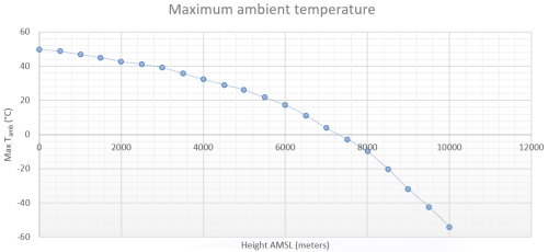
WARNING: Delta Elektronika power supplies are designed to fulfil the requirements of the IEC 60950, IEC 61010 and or the IEC 62368. The creepage and clearance distances inside the power supply are based on the tables up to 2000 meters above sea level. To use Delta Elektronika power supplies above this height, the customer should verify all creepage and clearance distances and take appropriate measures if the requirements are not fulfilled.
Temperature wise, one should derate the maximum allowable ambient temperature when operating more than 2000 meters above sea level. The maximum ambient temperature of our power supplies is usually 50 °C. This might be lower if the power supply has option P069 increased output current. At higher altitudes, the cooling capacity is reduced, due to lower air density, lower air pressure and decreased convection and advection. The graph below shows the relation between maximum ambient temperature (°C) and height (meters above mean sea level).
No, power supplies are complex instruments with numerous safety and protection circuits that can only be tested with special equipment. For a reliable repair, please send the unit back to the factory. The RMA-form can be found here.
We repair against real costs. For repairs that are not covered by warranty, we ask for your approval as soon as we diagnosed the defects.
We will not. Fuses blow for a reason. Replacing the fuse with a new one, without repairing the power supply first, will likely cause more damage. Please send your power supply for repair using the RMA form.
We treat all repairs as urgent, and the unit will be returned as soon as possible. We do not compromise on reliability and that means that each power supply that has been repaired, must undergo several tests to guarantee safety and reliability. This includes a burn-in (thermal soaking) test that takes several days.
The power supplies are protected against overheating. Multiple temperature sensors that monitor the temperature continuously. In case of overheating, the power supplies give a warning first. When the temperature limit is exceeded, the power supply will switch off to prevent damage. The unit might seem hot, but that is normal. For maximum stability, we let the heat sink temperature rise first and then stabilize it with a temperature-controlled fan around 60-70°C.
Most likely, it is not. Fans are temperature controlled and only start when the unit reaches its set point temperature. When there is no temperature warning, the power supply is functioning properly. Temperature-controlled fans generate less noise and have a longer lifetime.
All power supplies are factory calibrated and meet the specifications as published in the datasheet. A document that states this is available on request. This document mentions serial number, unit name and purchase date.
An interface card needs to be calibrated in the power supply to ensure maximum accuracy. Therefore, you cannot do this yourselves. On older units, it might not be possible to retrofit a new interface due to compatibility issues. You can contact the local sales representative for possibilities and pricing.
Our power supplies do not need calibration. The specifications as published in the datasheet are fixed by design. Those calibrations can only be influenced due to severe overload or repair. Delta Elektronika is not an accredited calibration facility. We can do the factory calibration, but when your QA system requires calibration according to certain standards, you need to go to an accredited calibration lab. The calibration procedure can be found in the manual.
The answer to this question is dependent on the application of the power supply. During repairs, it is often possible to determine which components are defective. However, to determine the root cause, information on the application is often required. We are eager to receive answers to the following questions:
- What is the application?
- What are the working conditions?
- What is the mains voltage, and what is the maximum voltage variation on it? Is the power supplied from a grid or a generator?
- What is the maximum output voltage and current during operation?
- What is the nature of the load, and what are the load characteristics?
By sending us this information and all other things that might have contributed to the defect, we may be able to suggest improvements or improve our products. If we cannot determine the root cause right away, we keep the information to assess if it occurs more often. This way, we can improve the durability of our products even further.
Improve the lifetime of a power supply
Delta Elektronika power supplies are equipped with protective circuits for transients, and they fulfill all requirements for immunity. However, in industrial environments, the grid quality may not be according to the specifications. Switching transients, lightning strikes and other distortion that is outside grid specification may cause extra defects over time.
On the DC-side engine cranking transients, DC-line transients and reverse polarity can occur. When unexplained failures occur, logging of in- and output voltages using a high sampling rate might reveal the root cause of the failure. Sending us this measurement data with reference to the RMA number is appreciated.
The power supply has a high efficiency that remains high over a broad range of output power. At low output power, the amount of power takes by the internal circuits, displays, fans etc becomes more significant and thus the efficiency drops.
Updating power supplies to the latest firmware version will ensure maximum functionality, the latest bug fixes and best performance. Since the firmware is backwards compatible, you will never lose functionality. In some cases, especially when the firmware on the device is old, special actions may be required. Please read the installation instructions carefully!
Most likely, the oscillations is caused by a resonant effect. The combination of output capacitance of the power supply, wiring inductance and load characteristics can easily form a resonant circuit agitated by the pulsating current of the inverter. A possible solution is adding a big capacitor close to the inverter. This minimizes the AC content of the current though the cables. In addition to that, thick, low inductive cabling may improve the results as well.
Remote sensing is not recommended in this case.
Although our power supplies have a good long term current stability, some applications require even better performance. This can be achieved using an external current sensor such as a zero-flux DC-Current Transformer. By adding or substracting the current error to the current setpoint, some customers claim to reach a long term stability of 1ppm.
Magnets are highly inductive loads. The ripple current depends on the impedance and time constant of the magnet. Superconductive magnets for example, have a very long time constant and the current cannot change quickly. This reduces the current ripple.
Normal inductors will also reduce the current ripple. The higher the switching frequency, the higher the suppression of the current ripple. Of course, every inductor has its specific behaviour and is a complex combination of inductance, resistance and capacitance. Therefore, we cannot give an indication of what the ripple will become.
Our analog interfaces are standardized on 0-5V (optionally 0-10V). The accuracy is specified as shown below. Assume this interface is used on an SM100-AR-75, a 100V, 75A power supply.
Programming accuracy
Programming accuracy is +/- 0.2%. If exactly 5V is applied to the Vprog input, the output voltage can be between 100V-0.2% = 99.8V and 100V+0.2% = 100.2V. However, due to offsets, zero volts on the input does often not result in zero volts on the output. It might take some voltage before the output voltage reacts.
Temperature drift
The offset has a temperature coefficient too. It drifts slightly when the temperature changes. Normally, ambient temperature does not change enough to make the temperature drift dominant. However, if the power supply is switched on at low temperatures, and the ambient temperature rises over 30 °C or more, the drift can be added to the offset voltage and accuracy to calculate the effect on the output voltage.
Monitoring output
The monitor outputs work similar as the inputs.
Impedance
Input impedance of the programming inputs is high, ±10 MΩ. Assume your programming source has an output resistance of 100Ω, the voltage loss over this 100Ω is 100/10M=0.001%
Although 100Ω is already quite high, the effect can be neglected. On the monitoring output, the impedance is 2Ω. Usually, input impedance of digital meters, data acquisition cards, loggers etc is very high, so this 2Ω can be neglected as well.
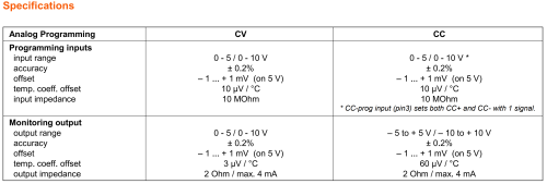
Accuracy specs of the INT MOD ANA interface
Example: Calculate the system accuracy at low and high voltage
Assume an offset of ±1mV: If the offset is -1mV, exactly zero volts on the input will lead to 1mV x 100V/5V= 20mV of output voltage. If the offset is +1mV, zero volts on the input would lead to -1mV x 100V/5V = -20mV, but the power supply can’t go negative, so the output is zero. Subsequently there must be at least 1mV on the input before the power supply will output any voltage.
In the example above, the input offset adds or subtracts 20mV to the output voltage. Instead of 99.8 to 100.2V, it can be 99.780V to 100.220V. The system accuracy containing the accuracy and offset now equals ±0.22%. At lower output voltages, the offset becomes more prominent. For example, 10V is programmed (Vprog = 0.5V). The offset is still ±20mV. Accuracy of 0.2% adds or subtracts 10 x 0.2% = 20mV so the total deviation is 40mV or ±0.4%. The system accuracy is thus dependent on the desired output voltage.
NOTE: Temperature drift is omitted in this example.
NOTE: This description is valid for the standard analog interfaces of the SM800, SM1500, SM6000 and for the INT MOD ANA interface of the SM3300 and SM15K.
The sampling frequency is 10Hz. Power variations with a frequency higher than 1Hz might not be measured consistently. PWM controlled motors for example, will not result in an accurate reading.
The internal resistance feature is meant to simulate a non-stabilized voltage source. The output voltage drops as the load current increases, according to Ohm’s law V=I x R.
Example:
The voltage of a car battery for example drops significantly during starting of the engine. The high battery current creates a voltage drop across the internal resistance of the battery. The internal resistance simulation can be used to imitate the effect.
Any cable between the power supply output and the load has resistance. According to Ohm’s law, this creates a voltage drop over the cable. When this is not acceptable, remote sensing or leadless sensing can be used. However, you may get best results by increasing the cable diameter.
Remote sensing
Remote sensing uses separate wires to measure the voltage at the input of the device under test. By doing so, the voltage drop over the power cables can be compensated. However, this compensation is limited to ensure stability. Large voltage drops over cables are often accompanied with inductive behaviour. This might cause resonance when applying load steps, resulting in oscillation of the power supply.
Leadless sensing:
Using leadless sensing, one can compensate for the voltage drop over the wires by using ohms law. The power supply calculates the voltage drop using the output current and the cable resistance entered by the user. When the current increases, the output voltage of the unit will be increased according to the calculated voltage drop over the wire to ensure that the input voltage of the device under test equals the user set voltage.
Since this method requires an additional calculation, the response of the power supply will be slower. This might give a better result when the current is rapidly changing, or with the pulsed current taken by (PWM) motor drivers, inverters etc.
Our power supplies have a monitoring output on the analog interface that provides a voltage signal (Imon) of 0-5V, proportional to the output current. When the current is smooth, without fast variations, Imon is quite accurate. However, this is not necessarily the case when observing dynamic behavior.
Except the SM15K series, all power supplies use the same principle for current measurement. The current runs through a low resistance and very stable shunt resistor. The voltage across the resistor is amplified and filtered from switching noise and presented as Imon, where the voltage from 0-5V corresponds to an output of zero to nominal maximum current. The filtering may be suspected for unexpected current outputs, but that is not the main issue here. The shunt is located before the output filter capacitors. This is necessary to ensure the stability of the control loop. A side effect of this position is that the relatively large output capacitors are outside the current measurement circuit. A sudden increase of output current will first be supplied from the capacitors, and this part is not measured. Eventually, the charge taken from the capacitors is restored by the power supply and that current is measured. This has the same effect as a low pass filter.
The same happens when a voltage step is programmed. During the voltage rise, the charge current for the capacitors is measured too, but not part of the output current. During the transition towards a lower voltage on a unidirectional power supply, the discharge current of the capacitors is part of the output current, but not measured and not present in the Imon signal. For a bi-directional power supply, this current will partly be present on the Imon signal.
To conclude: The current monitor output Imon is accurate at stable load conditions but should not be considered real-time during transitions of voltage and/or current. For that, an external current sensor will be necessary.
Yes, many customers are using Siemens PLCs with our power supplies and interfaces. PLCs from before 2015 might have an insufficient signal level. Connecting the PLC to the power supply via an Ethernet switch, resolves the problem.
Any kind of software capable of sending Ascii-strings to an Ethernet port can be used. The downloads section on the product page of our website offers a software package with a Labview executable and code examples for free.
There is not instrument driver (yet). Alternatively, use the sub-VI’s from the software that can be downloaded from the downloads section on the product page.
An ethernet port must be closed first before it can be re-opened. When a cable is disconnected or a switch is turned off, this might not be the case and reconnecting is not possible. The fastest way to reconnect is switch the power supply off, and on again. Best practice is of course to close the connection first, and then remove the cable.